 2016, Vol.3


2. Laboratory of Networked Control Systems, Shenyang Institute of Automation, Chinese Academy of Sciences, Shenyang 110016, China
There is much activity for electrical power generation to meet the ever increasing demand for electricity,which includes deployment of large amounts of unconventional energy resources (microturbines,photovoltaic,fuel cells,wind-power and storage devices)[1]. The unconventional energy resources are mostly inverter-interfaced and connected to the grid as distributed generation (DG). Microgrid are attracting a great deal of attention since they integrate these DGs in the main grid reliably and cleanly[1, 2, 3, 4]. In the microgrid,the distance between generation and loads is reduced,which can reduce losses,postpone investments in new transmission and large scale generation system[5]. Microgrid is beneficial to both the utility and customer. To the utility,the microgrid can operate as a single dispatchable unit to provide power or ancillary services; to the customers,it can improve power quality by supporting local voltage and frequency[6, 7].
The microgrid is a typical cyber-physical microgrid system (CPMS). In the physical component,some DGs (such as photovoltaic, wind-power) are affected by the external environment,thus they are intermittent and uncertain; most DGs are inverter-interfaced,thus they have lower inertia and more difficult to control than the traditional synchronous generators. In the cyber component,more and more advanced measurement and communication technologies are applied to the microgrid,however new algorithms and control strategies need to be proposed to make better use of the measured information from the grid. In order to ensure system-wide observability, controllability and stabilization for the microgrid,the cyber and physical component need to be integrated[8]. This new generation of microgrid system is CPMS. CPMS combines the cyber and physical component to obtain a common goal,the physical affects the cyber and vice-versa[9, 10]. With the substantial increase of the sophistication and diversity of control,communications,and power systems technologies in microgrid or smart grid[11],they have been studied as the cyber-physical system by several researchers[11, 12]. Liang et al. developed the testbed to evaluate the performance of a fully functioning cyber-physical system combining the control,communications,and power systems technologies[11]. Qu et al. proposed an algorithm for distributed data traffic scheduling with the awareness of linear dynamics state in CPSs and was applied in the multihop networks in the context of voltage control in microgrid[12],however,the authors did not deal with the active power distribution among the DGs in the microgrid.
For the physical component of CPMS,the challenge is to maintain the system voltage and frequency in both island and grid-connected modes. A lot of publications suggest that droop control methods are the best way to control DGs in microgrid[2, 13, 14, 15]. Droop control enables the micogrid to switch between the island mode and gird-connection mode smoothly and improve the grid transient performance. Furthermore,the droop-control method is applied in many demonstrated microgrids,which verified the effectiveness of droop control[1, 16].
For droop control methods,the inherent trade-off between power sharing and voltage and frequency regulation is one of its drawbacks. Nowadays,many researchers have focused on improving the droop control and many improved methods have been proposed. The modified droop controller was discussed in [17, 18, 19, 20, 21, 22],but the frequency and voltage amplitude have deviations in steady state. A restoration control was proposed in [23, 24],but this restoration control must be carried out by means of a central controller,which is complex and not reliable for single point of failure.
For the cyber component of CPMS,the challenge is to acquire the global information reliably without the effect of one critical equipment failure. The global information (such as the state, voltage and output power of each DG) are needed for the physical component of CPMS to restore the frequency and voltage deviations of droop control method. Generally speaking,the global information can be acquired by a distributed or centralized method. Although a centralized method can offer the possibility of implementing a basic management system for the global information discovery with lower costs of installation and operation than a distributed method,a distributed method can offer a plug and play performance which involves lower costs related to modifications in the microgrid's architecture[1]. Multi-agent system (MAS) is popularly used to get such global information distributedly. During the information discovery process,the agents only need to communicate with their corresponding neighbors. Furthermore,the global information discovery algorithm is independent of the system configuration,thus it can be applied to the microgrid system of any structures,such as radial,mesh and mixed. Over the past years,several global information discovery algorithms based on MAS have been proposed and applied to the microgrid[25, 26, 27]. The convergence,robustness and stability analysis of the MAS based algorithms were discussed in [27, 28, 29] for information discovery,which is helpful for the application to microgrid.
In the physical component,the droop controlled microgrid has steady deviations,and the droop curves of each DG can be shift up/down to restore the microgrid frequency and voltage. The quantization for shifting each DG’s droop curve depends on the global information which can be acquired by MAS in the cyber component of CPMS. Thus, the physical and cyber components can work properly together to realize the normal operation of the microgrid. The process to shift the droop curves of each DG using the global information acquired through MAS to maintain the normal frequency and voltage profile is similar for the AGC and AVC of the traditional main grid,thus we name this process as AGC and AVC for the microgrid. The AGC & AVC of microgrid plays a significant role in maintaining scheduled system frequency and voltage during normal operating condition[30]. Mallesham et al. proposed an AGC algorithm of microgrid using artificial intelligence techniques[30],however it is a heuristic algorithm which cannot acquire the optimal solution. Kumar et al. proposed a PI controller for the DGs to perform satisfactorily in a range of operating conditions to enable AGC[31]. However,in practical situations when the DGs are not connected to the microgrid at the same time,the integrator initial conditions are different,and,as a consequence,power sharing is degraded.
In order to verify the proposed model and algorithm,a typical low voltage benchmark microgrid system was built by using PSCAD/EMTDC. The simulation results show that the microgrid can operate in both island mode and grid-connected mode,and the two modes can shift smoothly. Furthermore,the voltage and frequency of the microgrid can be restored; meanwhile,the active power can be dispatched appropriately in both operating modes based on the capacity or the running cost of the DGs.
The main novel contributions of this paper are: 1) The microgrid was modeled as CPMS,the cyber part (MAS based distributed automatic generation control) can deal with the uncertainty and topological changes of the physical part (connection and disconnection of circuit breaker). 2) In the cyber component of CPMS,the global information discovery algorithm based on MAS is applied for each DG to discover the global information,AGC and AVC can deal with the drawback of traditional droop control distributedly by using the acquired global information; 3) The transient and steady state performances of CPMS are verified by simulations. It is shown that the cyber and physical components of CPMS work properly together and have better performance than traditional droop control methods.
This paper is organized as follows. In Section II,cyber-physical microgrid modeling and control are presented. Section III proposes the MAS-based global information discovery algorithm. Section IV presents the simulation and results. Finally,Section V concludes this paper.
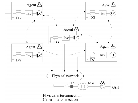
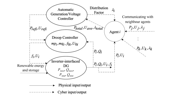
II. CYBER-PHYSICAL MICROGRID MODELING AND CONTROLThe modernization of the microgrid implies linking new concepts of communications,control,and computing[9]. In this paper,we recognize that,the centralized microgrid control mode will be very complex to design,if more advanced functions or real-time tasks are required. Thus,we propose a distributed cyber physical microgrid model as shown in Fig. 1.

|
Download:
|
| Fig. 1. Distributed cyber physical microgrid model. | |
In Fig. 1,the solid line represents the physical interconnection,while dashed line represents the cyber interconnection. The cyber world and physical world have the same goal and work properly together as a whole CPMS.
In the physical world,renewable energy (such as photovoltaic, fuel cells and wind-power) sourced DGs and storage units (battery, fly wheel) sourced DGs and loads constitute a microgrid which can operate in island mode or connect to the main grid through point of common coupling (PCC). The renewable energy sourced DGs and loads are intermittent and uncertain,which will cause the dynamic fluctuation of frequency and voltage of the microgrid. Furthermore,the change of state (open or closed) for circuit breaker in the feeder will change the topology of the physical world of microgrid. Thus,the physical world need cyber world to keep security and reliability.
In the cyber world,the system performances are monitored and controlled to keep the microgrid operate steadily and reliably through a wired/wireless communication network. The control architecture of the microgrid consists of local controller (LC), droop controller and MAS based automatic generation controller. Each DG in the microgrid has an agent,which is responsible for communicating with the neighboring agents. The global information (such as the average voltage and the output active power of the microgrid and so on) required for AGC and AVC can be acquired distributedly by MAS based global information discovery algorithm.
The fluctuation of loads and renewable energy sourced DGs in the microgrid cause an unbalance between supply and demand of active and reactive power in the microgrid. The unbalanced power should be timely dispatched among the DGs in the microgrid to keep the frequency and voltage of the microgrid steady,because the inertia of inverter-interfaced DGs are very low. Thus,the distributed global information discovery algorithm and controllers in the cyber world make the steady operation of the physical world feasible.
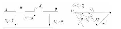
A. Droop ControlThe values of the active and reactive powers flowing between two AC voltage sources,which are connected in parallel through line impedance as shown in Fig. 2,can be calculated by (1) and (2)[32, 33]. In Fig. 2,$R$ and $X$ are line impedance and inductance respectively. $U_{1}$ and $U_{2}$ are the root-mean-square (RMS) value of the AC voltage sources,and their phases are $\theta_{1}$ and $\theta_{2}$ respectively. If $X{\gg}R$ and $\delta=\theta_{1}-\theta_{2}$ is small,then (1) and (2) can be simplified as (3) and (4).
| $P = \frac{{{U_1}}}{{{R^2} + {X^2}}}\left[{R\left( {{U_1} - {U_2}{\rm{cos}}\delta } \right) + X{U_2}{\rm{sin}}\delta } \right],$ | (1) |
| $Q = \frac{{{U_1}}}{{{R^2} + {X^2}}}\left[ { - R{U_2}{\rm{sin}}\delta + X\left( {{U_1} - {U_2}{\rm{cos}}\delta } \right)} \right],$ | (2) |
| $P = \frac{{{U_1}{U_2}}}{X}\delta ,$ | (3) |
| $Q = \frac{{{U_1}^2 - {U_1}{U_2}}}{X}.$ | (4) |

|
Download:
|
| Fig. 2. Power flow and the vector diagram between the main grid and the inverter interfaced DG. | |
As it is shown by (3) and (4),the active power,flowing from voltage source $1$ to $2$ through a highly inductive line impedance,can be controlled by varying the phase $\delta$. The reactive power supplied by source 1 can be controlled by controlling the magnitude of source $1$ ($U_{1}$). This is the basis of the conventional $P$ vs. $f$ and $Q$ vs. $V$ droop control,as shown in (5) and (6). In most cases,$f_{oi}$ and $U_{oi}$ are the nominal values[21].
| ${f_i}^* = {f_{oi}} + m{p_i}\left( {{P_{oi}} - {P_i}} \right),$ | (5) |
| ${U_i}^* = {U_{oi}} + m{q_i}\left( {{Q_{oi}} - {Q_i}} \right),$ | (6) |
where $i$ is the DG index,$mp_{i}$ and $mq_{i}$ are droop parameters,$U_{i}$,$f_{i}$,$P_{i}$,and $Q_{i}$ are the bus RMS voltage,the system frequency,and the locally measured active and reactive powers,respectively,and the subscript $o$ represents the preset values of normal operating points.
The angle $\delta$ is generated by controlling the frequency of source $1$ dynamically. The relation between the frequencies of the two interconnected AC voltage sources and $\delta$ is given by (7).
| \begin{align} \delta = 2\pi \int (f_{1}-f_{2}) \mathrm{d} t. \end{align} | (7) |
In order to avoid that the inverter is made to work over its capacity,the problem of reaching maximum output power needs to be addressed.
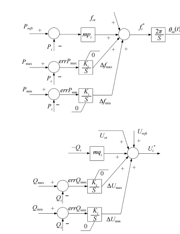
Fig. 3 is the proposed $P$ vs. $f$ and $Q$ vs. $U$ droop control diagram. In Fig. 3,$P_{\rm max}$ is the allowed maximum output power,$P_{i}$ is the output active power of the $i$th inverter, $errP_{\rm max}$ is the value of $P_{\rm max}$ minus $P_{i}$. If the power is larger than maximum,$errP_{\rm max}$ negative and the integral start generating a negative value for the offset. This offset in turns translates the droop curve down. It keeps on translating down until the offset exactly matches the value for which $errP_{\rm max}=0$. As long as it is not,the integral keeps on increasing the offset. When power output matches maximum power, the error becomes zero and the integral stops increasing the offset: a new steady state has been reached with offset ${\Delta}f_{\rm max}$. When preventing injections of power exceeding minimum value, the approach used to calculate the offset ${\Delta}f_{\rm min}$ is very similar to the approach used to calculate ${\Delta}f_{\rm max}$. To prevent the reactive power from reaching the maximum or minimum values,we take the same strategy,as shown in Fig. 3.

|
Download:
|
| Fig. 3. Adaptive P vs. f and Q vs. U droop control diagram. | |
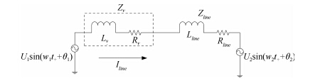
For direct coupled DG units,the impedance between two DGs is just the low voltage distribution feeder and has the relation of $R{\gg}X$. If we still want to use the $f(P)$ strategy,a physical coupling inductor or virtual coupling inductor should be added between the inverter terminals. These physical coupling inductors increase the size and weight of the system. The virtual impedance creates a ``voltage drop'' without generating real active and reactive powers losses and it is insensitive to the nature of the line impedance[33]. These physical inductances can be replaced by a virtual impedance[1] and consecutive virtual impedance variations[32, 33, 34, 35]. Therefore,a virtual impedance loop is added to the real line impedance as Fig. 4 shows.

|
Download:
|
| Fig. 4. Virtual impedance in series with the real line impedance. | |
In Fig. 4,$Z_{v}$ is the virtual impedance,$R_{v}$ is the resistive part of the virtual impedance,$L_{v}$ is the inductive part of the virtual impedance; $Z_{line}$ is the line impedance, $R_{line}$ is the resistive part of the line impedance,$L_{line}$ is the inductive part of the line impedance.
For droop control methods,the inherent trade-off between power sharing and voltage and frequency regulation is one of its drawback. In this paper,for AGC and AVC,MAS based global information discovery algorithm is used to acquire the global information,and it is described in Section III. There are two kinds of global information to be discovered: status information (such as the state of each DG and weight factor to dispatch active load) and performance metric (such as the average voltage and the output active power of the microgrid).
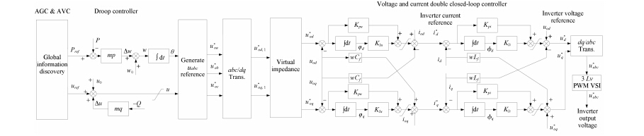
B. MAS Based AGC and AVCFig. 5 shows the cyber physical model of the controllable DGs. The DGs are controlled by three level controllers,the control diagram is shown in Fig. 6. As shown in Fig. 5 and Fig. 6,the first level is the voltage and current double closed-loop controller; the second level is the droop controller; the third level is the AGC and AVC controller. As shown in Fig. 5,the agent can get the global information by communicating with the neighboring agents. The AGC and AVC generate the active power and voltage reference for the droop controller by using the global information. The droop controller generates the three phase sine voltage references through the $P$ vs. $f$ and $Q$ vs. $U$ droop. Voltage and current double closed-loop controller tracks the voltage references. The detailed voltage dynamic equations and the method to choose the parameters of voltage and current control loops in Fig. 6 can be found in our previous work[36]. In this paper we only discuss the level of MAS based AGC. As the speed of voltage and current controller are higher than the MAS based AGC,it is reasonable to discuss the level of MAS based AGC and suppose the parameters are well defined in the lower level voltage and current controllers.

|
Download:
|
| Fig. 5. Cyber physical DG model. | |

|
Download:
|
| Fig. 6. Control block for inverter-interfaced DGs. | |
For the AGC and AVC,the frequency and voltage need to be restored only if the microgrid is operating in island mode,because in grid-connected mode,the frequency and voltage are maintained by the main grid. In island mode,we assume that,the DGs in the microgrid are all running properly and within the upper and lower limit.
From Fig. 3,we can derive the $P$ vs. $f$ and $Q$ vs $U$ droop curves as (8) and (9).
| ${f_i}^* = {f_{oi}} + m{p_i}\left( {{P_{refi}} - {P_i}} \right),$ | (8) |
| ${U_i}^* = {U_{oi}} - m{q_i} \cdot {Q_i} + {U_{loadrefi}}.$ | (9) |
Equation (8) is rewritten as follows:
| \begin{align} \Delta {f_i} = {f_i}^* - {f_{oi}} = m{p_i}\left( {{P_{refi}} - {P_i}} \right). \end{align} | (10) |
Assume:
| ${P_{total}} = \sum\limits_{i = 1}^n {{P_i}} ,$ | (11) |
| ${\lambda _{total}} = \sum\limits_{i = 1}^n {{\lambda _i}} ,$ | (12) |
where $n$ is the number of DGs running in the microgrid, $\lambda_{i}$ is the weight factor to share all the active power consumed by the load,which is decided based on the capacity or the running cost of the DGs.
If
| \begin{align} \label{13} {P_i} = {P_{total}} \cdot\frac{\lambda_i}{\lambda_{total}}, \end{align} | (13) |
then
| \begin{align} \label{14} {P_{refi}} = {P_{total}} \cdot \frac{\lambda_i}{\lambda_{total}} + \frac{\Delta f_i}{mp_i}. \end{align} | (14) |
After restoration of frequency,${\Delta}f_{i}$ is zero. Thus, $P_{refi}$ is rewritten as (15).
| \begin{align} \label{15} {P_{refi}} = {P_{total}} \cdot \frac{\lambda_i}{\lambda_{total}}. \end{align} | (15) |
Through global information discovery process implemented by MAS (as mentioned before),$P_{total}$ and ${\lambda}_{total}$ can be acquired by the AGCs for the DGs in the microgrid. ${\lambda}_{i}$ are local parameters,which can be adjusted online. Opposed to the frequency,the voltage of microgrid is not a global parameter[37]. In order to restore the voltage,global information discovery algorithm is implemented based on MAS to derive the average voltage $U_{aver}$ for the AVCs. A proportional-integral (PI) controller is used to calculate $U_{refi}$ and restore the average voltage of the microgrid to the presetted value. The relation between $U_{aver}$ and $U_{refi}$ are given by the following equations.
| ${U_{aver}} = \frac{{\sum\limits_{i = 1}^n {{U_i}} }}{n},$ | (16) |
| ${U_{refi}}\left( {\rm{s}} \right) = \left( {{U_{set}} - {U_{aver}}} \right) \cdot \left( {{K_{pres}} + \frac{{{K_{pres}}}}{S}} \right),$ | (17) |
where $K_{pres}$ and $K_{ires}$ are the PI controller parameters to restore the average voltage of the microgrid.
III. MAS BASED GLOBAL INFORMATION DISCOVERY ALGORITHMThe droop control has the drawback of trade-off between power sharing and voltage and frequency regulation. The AGC and AVC in high level were designed to restore the frequency and voltage to the normal values. Several proposed restoration control schemes are based on designing and implementing a central controller, which is complex and not reliable for single point of failure. In this paper,CPMS model was built,and based on this model,MAS based distributed AGC and AVC has been proposed. This method can restore the voltage and frequency and dispatch the active power properly by using the status information (such as the state of each DG and weight factor to dispatch active power) and performance metric (such as the average voltage and the output active power of the microgrid) discovered by the MAS based global information discovery algorithm.
In recent years,global information discovery algorithm based on MAS has attracted great interest in various areas[25, 38, 39]. The algorithm is a fully distributed one,each agent only need to communicate with their corresponding neighbors during the information discovery process. It is based on multiagent coordination and does not need a powerful central controller. Thus it is robust to the single point failures.
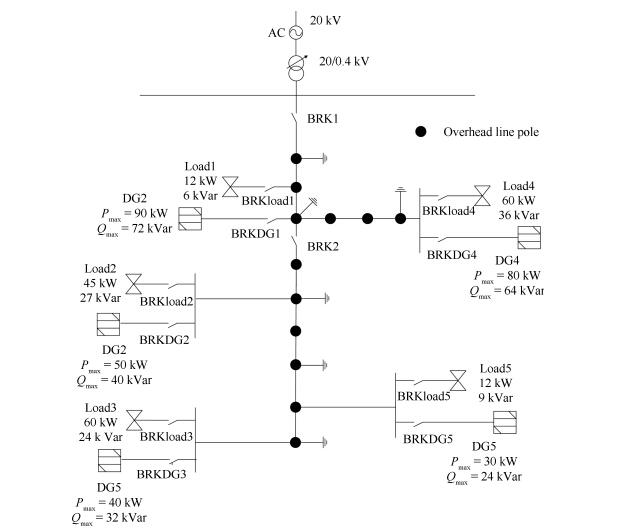
We take a typical benchmark Microgrid[40],as Fig. 7 shows, for research. The microgrid is coupled with the main grid through the PCC,and can operate either in the island mode or grid-connected mode. In Fig. 7,BRK1 and BRK2 are circuit breakers,BRK1 can permit the controlled connection and isolation of microgrid from the main grid; BRK2 can permit the case study of selective isolation of faulted parts of this microgrid. There are 5 DGs and 5 loads in the microgrid. The impedance data for various line types used in the network are given in [40],the capacities of DGs and the load demand are shown in Fig. 7. In this paper,it is assumed that each DG unit in the microgrid is assigned with an agent. Every agent knows local information,such as voltage, output active power and so on,but does not have direct access to the global information. Each agent can communicate with the neighbor agents. For example,in Fig. 7,DG 1 can communicate with DG 2 and DG 3. All agents form a MAS. It should be noted that,the designed communication network topology should satisfy the $N-1$ rule[41],thus the distributed algorithm can still work properly if any one of communication link is disabled. The original data of each DG for case study are summarized in Table I.

|
Download:
|
| Fig. 7. Topology of a microgrid. | |
|
|
Table I DATA OF EACH AGENT TO COMMUNICATE |
In the global information discovery algorithm,the information discovery process for the $i$th agent is represented as (18).
| \begin{align} \label{18} x_i^{k + 1} = x_i^k + \mathop \sum \limits_{j \in {N_i}} {a_{ij}}\left( {x_j^k - x_i^k} \right), \end{align} | (18) |
where $x_i^k$ and $x_j^k$ are the local information discovered by agent $i$ and $j$ at iteration $k$,respectively; $i=1,2, $...$,n$; $n$ is the number of agents in the microgrid; $x_i^k$ is updated to $x_i^{k+1}$ at iteration $k+1$; $a_{ij}$ is the coefficient for information exchanged between neighboring agents $i$ and $j$; $N_i$ is the set of neighbors for agent $i$.
The coefficient $a_{ij}$ plays an important role for the convergence speed. Xu et al. summarize and discuss several methods to design the coupling coefficients[27]. $a_{ij}$ is updated based on (19),as proposed in [27].
| \begin{align} \label{19} a_{ij}=\begin{cases} \frac{2}{{\left( {{n_i} + {n_j} + \varepsilon } \right)}},& \text{$j {\in} N_i$},\\ 1 - \mathop \sum \limits_{j \in {N_i}} \frac{2}{{\left( {{n_i} + {n_j} + \varepsilon } \right)}},& \text{$i=j$},\\ 0,& \text{otherwise}, \end{cases} \end{align} | (19) |
where $n_i$ is the number of neighbors for agent $i$. $\varepsilon$ is a very small number. Based on the consensus theory,the overall information discovery process can be modeled as a discrete time linear system as shows in (20).
| \begin{align} \label{20} {X^{k + 1}} = D \cdot {X^k}, \end{align} | (20) |
where $X^k$ is the vector of discovered information at the $k$th iterations; $D$ is the Laplacian matrix of the multiagent network graph[39]. The convergence speed is determined by the second largest eigenvalue of $D$.
The global information discovery algorithm can guarantee convergence for system of any size and topology,as shown in [26, 27]. In this paper,the information discovery process terminates once the following equation is valid:
| \begin{align} \left. {\left| {x_i^{k + 1} - x_i^k} \right.} \right| < \gamma, \end{align} | (21) |
where $\gamma$ is a small real number that defines the precision requirement.
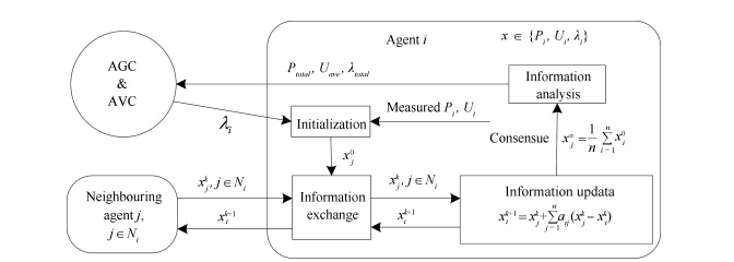
The global information discovery algorithm is implemented using the agents assigned to the DGs. The function modules of the agents and the MAS based AGC and AVC are illustrated in Fig. 8. In Fig. 8,the initialization module is initialized by the local information vector measured in the DG. The information update module acquires the information from the information exchange module. The information update module will keep updating the information vector till it converges. The converged information is the global information and is sent to AGC and AVC.

|
Download:
|
| Fig. 8. Function modules of the agents for global information discovery. | |
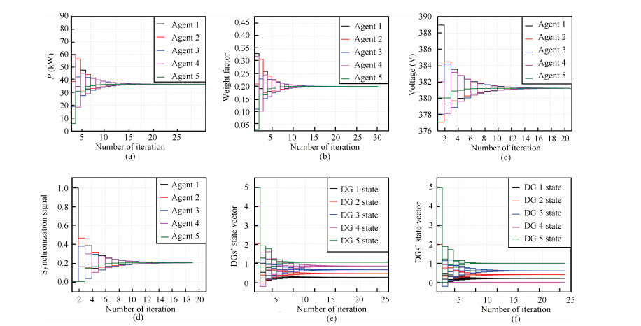
For the operation of AGC and AVC and DG status identification,there are two kinds of information to be discovered: status information and performance metric[11]. In order to acquire the information of how many DGs and which DGs are running in this microgrid,each agent in the microgrid is assigned with a unique state vector beforehand. In the beginning,agent $i$'s $N$-dimensional ($N$ is the total number of agents in the microgrid and it is a constant for a given microgrid) state vector $s_i$ only has one nonzero element at $(i,1)$ with the value of $i$,that is $s_i=[0,0,{\ldots},i,{\ldots},0]^{\rm T}$[26]. The $i$th elements of the state vector will converge to $i/M$ ($M$ is the total number of working agents in the microgrid,$M{\leq}N$),by applying the global information discovery algorithm to the same elements of the state vectors,as Fig. 9 (e) shows. When the DG 4 is disconnected (Agent 4 is still working normally),Agent 4's state vector $s_4$ is reset to be $[0,0,0,0]^{\rm T}$. By applying the global information discovery algorithm to the same elements of the state vectors,all the elements except for the 4th element of the state vectors will converge to the same value $i/M$ as before,as one can see in Fig. 9 (f). By checking the positions of zeros,all agents will know that the DG 4 is now disconnected,and the number of DGs connected to the microgrid $n$ is updated. Furthermore,by comparing the $i$th element with $x_i/M$,where $x_i$ can be either $i$ or $0$ (when the corresponding DG is disconnected) and $M$ may be any integer between 1 and $N$,thus one can find the $M$ matches the converged state vector $[x_1/M,~x_2/M,\ldots,x_i/M,\ldots,x_N/M]^{\rm T}$. Thus,the number of working agents $M$ can also be found. Multiply the discovered average performance metrics by $M$,the total value of metrics can be derived accordingly.

|
Download:
|
| Fig. 9. Information discovery processes of status information and performance metrics: (a) average active power discovery process; (b) average weight factor discovery process; (c) average voltage discovery process; (d) synchronization signal discovery process; (e) DGs’ state vector discovery process, when all DGs are connected to the microgrid; (f) DGs’ state vector discovery process, when DG4 is disconnected from the microgrid. | |
If an agent fails to communicate with all of its neighbors,the rest agents can acquire the total output active power $P_{total}^1$ and total weight factors $\lambda _{total}^1$ of the rest DGs with normal agents (If the designed communication network topology of the MAS satisfies the $N-1$ rule). For the DG whose agent is fault can be seen as an negative load,the frequency deviation and voltage deviation can also be eliminated by the other generators with normal agents. When a communication link fails for a certain agent,the proposed AGC/AVC scheme can still work properly,if the designed communication network topology of the MAS satisfies the $N-1$ rule.
All the agents need send heartbeat packet to its neighbors,then each agent knows who are its neighbors and the number of neighbors at present. By using the (19),$a_{ij}$ can be updated. It deals with the fault of agent loss. When the microgrid is expanded,it only needs to update its neighbors' information. Thus,MAS control offers a plug and play performance which involves low costs related to modifications in the microgrid’s architecture.
Agent 1 is responsible for synchronizing with the main grid. Agent 1's synchronization signal $Syn$ will be 1,when the microgrid is going to change from the island mode to the grid-connected mode, otherwise $Syn$ will be 0. Other agents' synchronization signal $Syn$ is always initialized to be zero. Thus,when the agent finds that $Syn$ converges to a nonzero value,all the droop controllers start to synchronize the microgrid with the main grid to prepare for connecting to the main grid. In order to deal with the possible fault of the agent connected with the main grid,one can set two agents to synchronize with the main grid. In order to simplify the discussion,we only set one agent in this paper. The information discovery processes of status information and performance metrics are shown in Fig. 9.
The data to communicate is represented by 16 bits for one data. There are 9 data to communicate by each agent,and we suppose the maximum number of iterations for convergence is 50 for the global information discovery algorithm which is rational considering the results in Fig. 9. Suppose that one agent has 10 neighbors at maximum in the microgrid. If we want to get the global information 5 times per second,the communicating rate should be higher than $16{\times}9{\times}50{\times}10{\times}5{\times}2=720 {\rm kbps}$. Nowadays,the communicating rate of $720 {\rm kbps}$ is easy to fulfill. Thus,it is reasonable to get global information 5 times per second.
IV. SIMULATION AND RESULTSThe microgrid is modeled as a distributed cyber physical microgrid system. According to the model,the MAS based AGC and AVC for the microgrid have been proposed. In order to verify the proposed model and algorithm,we implement the microgrid system in Fig. 7 by using PSCAD/EMTDC. The microgrid contains five inverter-interfaced DGs with PWM voltage source inverters. The DGs in the microgrid are coordinated via $P$ vs. $f$ and $Q$ vs. $U$ droop controllers and the global information are discovered by MAS.
In this paper,the inverter is fed by a DC bus voltage source of 750 V,which emulates the combined effects of a prime mover and an energy storage. The carrier frequency of inverter is 5000 Hz. The rated power factors of the DGs are all set as 0.8; the minimum operating frequency is 49.5 Hz,which is 0.5 Hz below nominal frequency.
The fixed slopes $mp_i$ of the $P$ vs. $f$ droop are chosen to be the value of the slop obtained for $P_{refi}=0$ in (8),which are listed in Table II.
|
|
Table II DGs’ DATA SUMMARY |
When the value of the maximum offset expected for the voltage, ${\Delta}E$,is known,with $Q_{\rm max}$,the slopes $mq_i$ of the $Q$ vs. $V$ droop can be determined by $\Delta E/Q_{\rm max}$. The maxmium offset for the voltage is taken as the difference in voltage between the best and worst case scenarios[3]. The best case scenario is that the microgrid is fully energized from the grid,without microsources and without loads. The worst case scenario is that the microgrid is energized from the grid,without microsources and with all the loads. The voltages in the best case scenario are represented as $V_{\rm max}$,in the worst case scenario they are represented as $V_{\rm min}$. $V_{\rm max}$, $V_{\rm min}$ and the slopes $mq_i$ are listed in Table II.
As (3) shows,the phase angle difference ${\delta}$ is affected by the coupling inductor $X$. The angle difference ${\delta}$ cannot be allowed to get too small to avoid errors caused by imprecise measurement of ${\delta}$. In order to have a good linear approximation between $P$ and ${\delta}$,${\delta}$ cannot be allowed to get too big,either. In this paper,${\delta}$ is set to be 7 degrees at full ratings. This means the virtual impedance $X$ can be calculated as (22) shows. The virtual impedances $X$ are calculated and listed in Table II.
| \begin{align} X = \frac{{{U_1}{U_2}}}{{{P_{\rm max}}}}{\delta _{\rm max}}. \end{align} | (22) |
The other parameters used in this paper are given in Table III.
|
|
Table III OTHER PARAMETERS |
We set the simulation sequence as follows: 1) 0 s-2 s,the microgrid is operating in island mode and all DGs and loads are connected; 2) At the 3rd second,DG 2 is disconnected and it is not connected to the main grid again; 3) 2 s-6.8 s,all DGs start to synchronize the microgrid with the main grid,in order to get ready to be connected to the main grid; 4) 6.8 s-13 s,the microgrid is connected to the main grid and we set each DG to output 10 kW active power and set DG 1,DG 3,DG 4 and DG 5 to output 10 kVar,8 kVar,3 kVar and 0 kVar reactive power,respectively; 5) 13 s-14 s,we assume the DGs have not detected the island to analyze the effect of time delay to the system; 6) At the 14th second,all DGs get the information of island,and recover the frequency and redispatch active power; 7) At the 17th second,load 3 is disconnected. In this simulation,the global information is acquired once every 0.2 seconds. The simulation results of the microgrid are shown in Figs. 10-13.
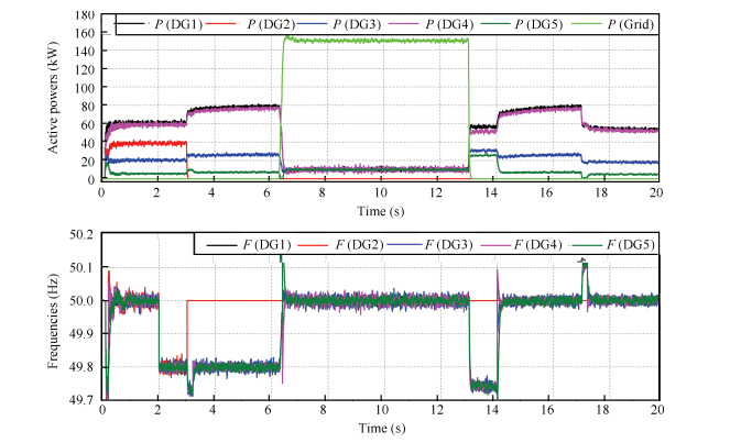
Fig. 10 shows the active powers and frequencies of DGs. In island mode,the frequency can be restored and the active powers can be dispatched as one wants,simultaneously. In grid-connected mode (during 6.2 s-13 s),the system frequency is provided by the main grid,the output active power of each DG can follow up the preset value,while the grid provides the residual load demand,thus the active power of the grid is about 150 kW and 0 kW when the microgrid is in grid-connected mode and island mode,respectively. When DG 2 is disconnected from the microgrid at the 3rd second,the other DGs increase their output active powers to compensate the active power for the microgrid. For the time delay of island mode detection during 13 s-14 s,the frequency is not restored but the system can still work properly. At the 17th second,when load 2 is disconnected,all DGs will decrease the output active power,while the frequency is higher than normal value for a little moment,then it is restored to normal value.

|
Download:
|
| Fig. 10. Active powers and the frequencies of DGs. | |
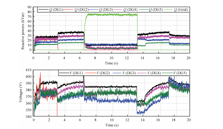
Fig. 11 shows the reactive powers and voltages of DGs. In island mode,when DG 2 is disconnected at the 3rd second,the voltages are decreased and are restored for a while. In grid-connected mode (during 6.2 s-13 s),the voltages are provided by the main grid and the output reactive power of each DG can follow up the preset value,while the grid provides the residual reactive demand,thus the reactive power of the grid is about 72 kVar and 0 kVar when the microgrid is in grid-connected mode and island mode, respectively. During 0 s-2 s,the microgrid is in island mode, Fig. 10 and Fig. 11 show that the frequency and average value of voltage magnitude can be recovered to the normal values in a very short time,which overcomes the drawback (steady frequency and voltage deviations) of traditional droop control method.

|
Download:
|
| Fig. 11. Reactive powers and voltages of DGs. | |
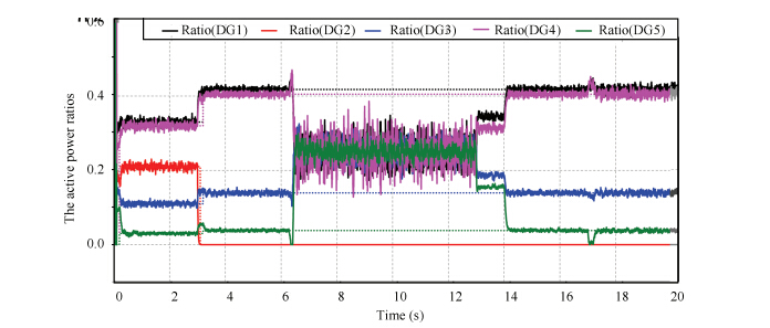
Fig. 12 shows the active power ratios of each DG. The dashed line represents the preset ratios and the solid line represents the actual active power ratios. We only need to see the moment when the microgrid is in island mode,because in grid-connected mode, each DG is set to output 10 kW active power. In this figure,we see that the DGs active power ratios can follow the preset values most of the time. During the time delay of island mode detection of 13 s-14 s the actual active power ratios cannot follow up the preset value,the difference between the actual ratios and actual ratios in other time is caused by the time delay of global information discovery. If the generators in the microgrid have sufficient reserve capacity,the AGC/AVC scheme will still work properly when the load fluctuates severely. Because the AGC/AVC is the second level controller (low speed) with responsibility of eliminating the frequency and voltage deviations caused by the first level droop controller (high speed). If the parameters for $P$ vs. $f$ and $Q$ vs. $V$ droop controllers are well optimized,the frequency deviation and voltage deviation will not exceed the permissible values. Thus the communication delay will only affect the time for eliminating the frequency and voltage deviations and does not affect the system safety and stability.

|
Download:
|
| Fig. 12. Active power ratios of DGs. | |
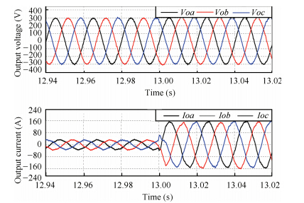
Fig. 13 shows the output voltage and current of DG1 when the microgrid disconnected from the main grid. The quality of the DG1's output voltage and current are high with few harmonics in both island mode and grid-connected mode.

|
Download:
|
| Fig. 13. Output voltage and current of DG1 when disconnected from the main grid. | |
In this paper,the microgrid was modeled as CPMS. Based on this model,the MAS based distributed AGC and AVC were introduced to overcome the drawback of traditional droop control. In the cyber component,the MAS based global information discovery was proposed to distributedly acquire the global information required by AGC and AVC. In the physical component,the droop control was proposed to control the DGs in the microgrid. The cyber component and physical component have the same goal and work properly together as a whole CPMS. The AGC and AVC can restore the voltage and frequency of the microgrid with the global information,meanwhile the active power can be dispatched properly,according to the capacity or the running cost of each DG. A typical low voltage benchmark microgrid system was built by using PSCAD/EMTDC to verify the proposed model and algorithm. The simulation results demonstrate that the proposed model and control method are effective.
| [1] | Planas E, Gil-de-Muro A, Andreu J, Kortabarria I, de Alegria I M. General aspects, hierarchical controls and droop methods in microgrids:a review. Renewable and Sustainable Energy Reviews, 2013, 17:147-159 |
| [2] | Zamora R, Srivastava A K. Controls for microgrids with storage:review, challenges, and research needs. Renewable and Sustainable Energy Reviews, 2010, 14(7):2009-2018 |
| [3] | Alanne K, Saari A. Distributed energy generation and sustainable development. Renewable & Sustainable Energy Reviews, 2006, 10(6):539-558 |
| [4] | Hatziargyriou N. MICROGRIDS-large scale integration of micro-generation to low voltage grids[Online], Available:http://microgrids.eu/micro2000/presentations/16.pdf, 2014. |
| [5] | Lasseter R H, Piagi P. Control and design of microgrid components[Online], Available:https://certs.lbl.gov/sites/all/files/ctrldesign-microgridcomponents.pdf, 2006. |
| [6] | Huang J Y, Jiang C W, Xu R. A review on distributed energy resources and microgrid. Renewable and Sustainable Energy Reviews, 2008, 12(9):2472-2483 |
| [7] | Justo J J, Mwasilu F, Lee J, Jung J W. AC-microgrids versus DCmicrogrids with distributed energy resources:a review. Renewable and Sustainable Energy Reviews, 2013, 24:387-405 |
| [8] | Ilić M D, Xie L, Khan U A, Moura J M F. Modeling of future cyber-physical energy systems for distributed sensing and control. IEEE Transactions on Systems, Man, and Cybernetics, Part A:Systems and Humans, 2010, 40(4):825-838 |
| [9] | Macana C A, Quijano N, Mojica-Nava E. A survey on cyber physical energy systems and their applications on smart grids. In:Proceedings of the 2011 IEEE PES Conference on Innovative Smart Grid Technologies (ISGT Latin America). Medellin:IEEE, 2011. 1-7 |
| [10] | Baheti R, Gill H. Cyber-physical systems[Online], Available:www.ieeecss.org, 2011. |
| [11] | Liang H, Choi B J, Zhuang W H, Shen X M, Awad A S A, Abdr A. Multiagent coordination in microgrids via wireless networks. IEEE Wireless Communications, 2012, 19(3):14-22 |
| [12] | Qu C, Chen W, Song J B, Li H. Distributed data traffic scheduling with awareness of dynamics state in cyber physical systems with application in smart grid. IEEE Transactions on Smart Grid, 2015, PP(99):1 |
| [13] | Peas Lopes J A, Moreira C L, Madureira A G. Defining control strategies for microgrids islanded operation. IEEE Transactions on Power Systems, 2006, 21(2):916-924 |
| [14] | Katiraei F, Iravani R, Hatziargyriou N, Dimeas A. Microgrids management. IEEE Power and Energy Magazine, 2008, 6(3):54-65 |
| [15] | Ustun T S, Ozansoy C, Zayegh A. Recent developments in microgrids and example cases around the world-a review. Renewable and Sustainable Energy Reviews, 2011, 15(8):4030-4041 |
| [16] | Lidula N W A, Rajapakse A D. Microgrids research:a review of experimental microgrids and test systems. Renewable and Sustainable Energy Reviews, 2011, 15(1):186-202 |
| [17] | Barklund E, Pogaku N, Prodanovic M, Hernandez-Aramburo C, Green T C. Energy management in autonomous microgrid using stabilityconstrained droop control of inverters. IEEE Transactions on Power Electronics, 2008, 23(5):2346-2352 |
| [18] | Diaz G, Gonzalez-Moran C, Gomez-Aleixandre J, Diez A. Scheduling of droop coefficients for frequency and voltage regulation in isolated microgrids. IEEE Transactions on Power Systems, 2010, 25(1):489-496 |
| [19] | Majumder R, Chaudhuri B, Ghosh A, Majumder R, Ledwich G, Zare F. Improvement of stability and load sharing in an autonomous microgrid using supplementary droop control loop. IEEE Transactions on Power Systems, 2010, 25(2):796-808 |
| [20] | Hasanzadeh A, Onar O C, Mokhtari H, Khaligh A. A proportionalresonant controller-based wireless control strategy with a reduced number of sensors for parallel-operated UPSs. IEEE Transactions on Power Delivery, 2010, 25(1):468-478 |
| [21] | Chung I Y, Liu W X, Cartes D A, Collins E G Jr, Moon S I. Control methods of inverter-interfaced distributed generators in a microgrid system. IEEE Transactions on Industry Applications, 2010, 46(3):1078-1088 |
| [22] | Golestan S, Joorabian M, Rastegar H, Roshan A, Guerrero J M. Droop based control of parallel-connected single-phase inverters in D-Q rotating frame. In:Proceedings of the 2009 IEEE International Conference on Industrial Technology. Gippsland, VIC:IEEE, 2009. 1-6 |
| [23] | Chandrokar M C, Divan D M, Banerjee B. Control of distributed UPS systems. In:Proceedings of the 25th Annual IEEE Power Electronics Specialists Conference. Taipei:IEEE, 1994. 197-204 |
| [24] | Guerrero J M, Vasquez J C, Matas J, de Vicuña L G, Castilla M. Hierarchical control of droop-controlled AC and DC microgrids-a general approach toward standardization. IEEE Transactions on Industrial Electronics, 2011, 58(1):158-172 |
| [25] | Xu Y L, Zhang W, Liu W X, Ferrese F. Multiagent-based reinforcement learning for optimal reactive power dispatch. IEEE Transactions on Systems, Man, and Cybernetics, Part C:Applications and Reviews, 2012, 42(6):1742-1751 |
| [26] | Xu Y L, Liu W X, Gong J. Stable multi-agent-based load shedding algorithm for power systems. IEEE Transactions on Power Systems, 2011, 26(4):2006-2014 |
| [27] | Xu Y L, Liu W X. Novel multiagent based load restoration algorithm for microgrids. IEEE Transactions on Smart Grid, 2011, 2(1):152-161 |
| [28] | Jain P, Ranade S J. Capacity discovery in customer-driven micro-grids. In:Proceedings of the 2009 North American Power Symposium (NAPS). Starkville, MS, USA:IEEE, 2009. 1-6 |
| [29] | Jain P, Ranade S J, Srivastava S K. Island identification in customerdriven micro-grids. In:Proceedings of the 2010 IEEE PES Transmission and Distribution Conference and Exposition. New Orleans, LA, USA:IEEE, 2010. 1-7 |
| [30] | Mallesham G, Mishra S, Jha A M. Automatic generation control of microgrid using artificial intelligence techniques. In:Proceedings of the 2012 IEEE Power and Energy Society General Meeting. San Diego, CA:IEEE, 2012. 1-8 |
| [31] | Kumar B S, Mishra S. AGC for distributed generation. In:Proceedings of the IEEE International Conference on Sustainable Energy Technologies. Singapore:IEEE, 2008. 89-94 |
| [32] | De Brabandere K, Bolsens B, Van den Keybus J, Woyte A, Driesen J, Belmans R. A voltage and frequency droop control method for parallel inverters. IEEE Transactions on Power Electronics, 2007, 22(4):1107-1115 |
| [33] | Guerrero J M, Matas J, Garcia de Vicuna L, Castilla M, Miret J. Decentralized control for parallel operation of distributed generation inverters using resistive output impedance. IEEE Transactions on Industrial Electronics, 2007, 54(2):994-1004 |
| [34] | Guerrero J M, Garcia de Vicuna L, Matas J, Castilla M, Miret J. Output impedance design of parallel-connected UPS inverters with wireless load-sharing control. IEEE Transactions on Industrial Electronics, 2005, 52(4):1126-1135 |
| [35] | Zhang X T, Zhang H, Guerrero J M, Ma X K. Reactive power compensation for parallel inverters without control interconnections in microgrid. In:Proceedings of the 34th Annual Conference of IEEE Industrial Electronics. Orlando, FL:IEEE, 2008. 922-925 |
| [36] | Li Z W, Zang C Z, Zeng P, Yu H B, Li H P. The controller parameters optimization for droop controlled distributed generators in microgrid. In:Proceedings of the 2nd International Conference on Renewable Energy and Environmental Technology. Switzerland:Trans Tech Publications, 2014. 1329-1335 |
| [37] | Vandoorn T L, De Kooning J D M, Meersman B, Guerrero J M, Vandevelde L. Automatic power-sharing modification of P/V droop controllers in low-voltage resistive microgrids. IEEE Transactions on Power Delivery, 2012, 27(4):2318-2325 |
| [38] | Xiao F, Wang L, Jia Y M. Fast information sharing in networks of autonomous agents. In:Proceedings of the 2008 American Control Conference. Seattle, WA:IEEE, 2008. 4388-4393 |
| [39] | Olfati-Saber R, Fax J A, Murray R M. Consensus and cooperation in networked multi-agent systems. Proceedings of the IEEE, 2007, 95(1):215-233 |
| [40] | Papathanassiou S, Hatziargyriou N, Strunz K. A benchmark low voltage microgrid network. In:Proceedings of the 2005 CIGRE Symposium. Athens, Greece, 2005. 1-8 |
| [41] | Zhang W, Liu W X, Wang X, Liu L M, Ferrese F. Online optimal generation control based on constrained distributed gradient algorithm. IEEE Transactions on Power Systems, 2015, 30(1):35-45 |