2. Changchun Institute of Optics, Fine Mechanics and Physics, Chinese Academy of Sciences, Changchun 130033, China;
3. University of Chinese Academy of Sciences, Beijing 100039, China;
4. Department of Control Science and Engineering, Jilin University, Changchun 130025, China
Recently,a quad-rotor UAV as the rotary wing UAV consisting of four individual rotors of "X" arrangement,has evoked a great interest in the research and academic circles due to its simple mechanical structure and attractive vertical take-off and landing capability[1]. Numerous applications of the quad-rotor have been steadily increasing in a wide range of areas such as surveillance,search,rescue and scout[2].
However,in practical situations,there are many difficult problems in controlling quad-rotor UAV because of the inevitable uncertainties[3]. Thus,the robust control problem has been increasingly considered for quad-rotor with model uncertainties and external disturbances[4, 5, 6, 7, 8, 9, 10]. A robust sliding mode flight controller with sliding mode disturbance observer was developed for a small quad-rotor[4]. This technique allows for a continuous control robust to external disturbance and model uncertainties without the use of high control gain or extensive computational power. Raffo et al.[5] proposed an integral predictive and nonlinear robust control strategy with a hierarchical scheme consisting of a model predictive controller (MPC) to track the reference trajectory together with a nonlinear $H_\infty$ controller to stabilize the rotational movements for a quad-rotor. The effectiveness and the robustness of the controller were corroborated by simulations in the presence of aerodynamic disturbances, parametric and structural uncertainties. Mohammadi et al.[6] used model reference adaptive control (MRAC) technique to control a quad-rotor in the case of various conditions with parametric and non-parametric uncertainties in the model. An accurate simulation including empirical dynamic model of battery, sensors,and actuators was performed to validate the stability of the closed loop system. A controller based on the block control technique combined with the super twisting control algorithm[7] has been proposed for the quad-rotor. The virtual control inputs and the wind parameter resulting from the aerodynamic forces have been estimated via the first order exact differentiator. Simulations and experiments verified the validity of the controller when faced with disturbances. Satici et al.[8] designed an $L_1$-optimal controller for a quad-rotor UAV that rejects persistent disturbances. The controller yields an exponential decrease of the magnitude of the errors in an $L_1$-optimal sense in the presence of parametric uncertainty and measurement noise. Liu et al.[9] designed a robust attitude control method combining PD control with the robust compensation for uncertain quad-rotors. The PD controller is aimed to achieve the desired tracking and the robust compensator is added to restrain the influence of the uncertainties. A simple robust quad-rotor controller[10] was provided using linear matrix inequalities to synthesize controller gains. The controller is based on approximate feedback linearization considering dynamic external disturbances,inexact nonlinearity cancellation,multiplicative actuator uncertainty and saturated integrators.
The aforementioned robust control methods are all based on the inherent structure of quad-rotor that leads to the deficiency in driving capability. This paper therefore develops a novel coaxial eight-rotor UAV with a new configuration. It is designed with eight rotors that are arranged as four counter-rotating offset pairs mounted at the ends of four carbon fiber arms in a cruciform configuration. The four sets of matched counter rotating rotor blades provide differential thrust from four equally spaced points,which allows the eight-rotor UAV to maneuver with higher agility. And it offers the advantage of markedly increased drive capability and greater ability to resist to disturbance owing to its added four rotors than quad-rotor in condition of using the same type of motors and rotors. As a result, the coaxial eight-rotor UAV has nearly twice overall thrust than a quad-rotor UAV without increasing the weight to double. Besides,the eight-rotor UAV has the same floor space as a quad-rotor UAV. Obviously,the higher coefficient proportion between thrust and gravity as well as the greater payload capacity are provided by the eight-rotor UAV as compared with a quad-rotor UAV in the case of the same type of motors and rotors. Furthermore,the coaxial eight-rotor UAV has dominant superiorities in terms of weaker degree of attitude coupling in the cruciform structure and stronger damage tolerance to have stable flight when some of rotors are broken,these features are not provided in quad-rotor UAV.
On this basis,a robust backstepping sliding mode controller (BSMC) with adaptive radial basis function neural network (RBFNN) is proposed to control the attitude of the coaxial eight-rotor UAV in the case of model uncertainties and external disturbances. As we know,the key feature of backstepping design is that it stabilizes the system states through a step-by-step recursive process[11]. Once the final step is completed,the stability of the entire system is guaranteed naturally[12]. However, conventional backstepping design with integral adaptive laws is no longer applicable when the derivatives of the model uncertainty and the disturbance cannot be regarded as zero[13]. Thereby, efforts to combine backstepping technique with sliding mode control (SMC) that has inherent insensitivity and robustness against disturbances under the matching conditions were made[14, 15]. Unfortunately,a prior knowledge of the uncertainty and disturbance bounds is required for the backstepping and sliding mode control. On account of these characteristics,adaptive RBFNN is introduced as the uncertainty observer in this research. It can effectively estimate the model uncertainties and external disturbances without the pre-knowledge of uncertainties bounds,which makes it possible to combine those two design methodologies to preserve their advantages and at the same time overcome their drawbacks mentioned above. Finally,the satisfactory robustness and attitude control performance of BSMC with adaptive RBFNN method are demonstrated via simulations in the case where the inertia matrix uncertainties as model uncertainties and external disturbance are taken into account.
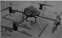
Ⅱ. DYNAMIC MODEL OF COAXIAL EIGHT-ROTOR UAVThe eight-rotor UAV in cruciform configuration consists of four pairs of coaxial double rotors,as shown in Fig. 1,where ${\rm{\Omega}}_i$,$i=1,2,\cdots,8$ is the speed of eight rotors respectively. Each pair of double rotors is counter rotating. Meanwhile,the two adjacent pairs of rotors rotate in opposite directions. That is,the rotors of 1,4,5,8 rotate clockwise, while the other rotors rotate counterclockwise. When the rotor speeds are together varied,the thrust will be changed,which will affect the altitude of the system. The pitch movement is obtained by increasing (reducing) the speed of the rear pair of rotors and reducing (increasing) the speed of the front pair of rotors,the roll angle can be obtained similarly using the remaining two pairs of rotors. The yaw movement is provided by speeding up or slowing down the speed of counter-clockwise rotors and changing the same speed of rotary clockwise rotors in the opposite direction depending on the desired angle direction,which in turn generates reactive torque. The translational movement depends on the change of pitch or roll angle.
|
Download:
|
| Fig. 1. The scheme of coaxial eight-rotor UAV. | |
There are two main reference frames defined to express the dynamics of eight-rotor UAV,as shown in Fig. 1: the earth-fixed inertial frame $E=\{O_{g}x_{g}y_{g}z_{g}\}$ and the body-fixed frame $B=\{O_{b}x_{b}y_{b}z_{b}\}$ both fixed at the centre of the aircraft. The translational position of the eight-rotor UAV is defined as $\pmb{\zeta}=[x,y,z]^{\rm{T}}$ and the attitude is expressed by three Euler angles $\pmb{\eta}=[\phi,\theta,\psi]^{\rm{T}}$.
Owing to the eight-rotor UAV treated as a symmetrical rigid body with six degrees of freedom,the nonlinear dynamics can be derived by using Newton-Euler formulas. The rotational dynamic equations of the eight-rotor UAV can be obtained by
| $ \begin{align} &\frac{{\rm{d}}\pmb{H}}{{\rm d}t}=\frac{{\delta}\pmb{H}}{{\delta}t}+\pmb{\omega}\times\pmb{H}= \nonumber\\ &\quad\quad\pmb{M}+ \pmb{\Delta{M_1}}+\pmb{\Delta{M_2}}, \end{align} $ | (1) |
where $\frac{{\rm{d}}\pmb{H}}{{\rm d}t}$ represents the absolute derivative of $\pmb{H}$ with respect to the inertial frame $E$,and $\frac{{\delta}\pmb{H}}{{\delta}t}$ the relative derivative with respect to the body-fixed frame $B$,with the angular momentum $\pmb{H}$ represented as
| $ \begin{equation} \pmb{H}=\pmb{J}\cdot\pmb{\omega}, \end{equation} $ | (2) |
and $\pmb{J}={\rm diag}(I_{x},I_{y},I_{y})$ as the moment of inertia along $x,y$ and $z$ directions. $\pmb{\omega}=[p,q,r]^{\rm{T}}$ denotes the angular velocity with respect to body-fixed frame $B$. $ \pmb{\Delta{M_1}}=[\Delta{M_{1x}},\Delta{M_{1y}},\Delta{M_{1z}}]$ expresses unmodeled dynamics such as gyroscopic effect and aerodynamic moments that actually is very complicated and hardly modeled. $ \pmb{\Delta{M_2}}=[\Delta{M_{2x}},\Delta{M_{2y}},\Delta{M_{2z}}]$ denotes external disturbances. From the above,by substituting (2) into (1),it can be derived that
| $ \begin{equation} \pmb{J} \cdot {\dot{\pmb\omega}} = -\rm{sk}(\pmb{\omega} ) \cdot \pmb{J} \cdot \pmb{\omega} + \pmb{M}+ \pmb{\Delta{M_1}}+ \pmb{\Delta{M_2}}, \end{equation} $ | (3) |
where $\rm{sk}(\pmb{\omega})$ is called as skew-symmetric matrix and defined as
| $ \begin{equation} \rm{sk}(\pmb{\omega})=\left[ \begin{array}{ccc} 0 & -r & q\\ r & 0 & -p\\ -q & p& 0\\ \end{array} \right]. \end{equation} $ | (4) |
Furthermore,the inertia matrix uncertainty is considered as the model uncertainty caused by the change in mass properties and is expressed as $\Delta\pmb{J}={\rm diag}{\Delta{I_x},\Delta{I_y},\Delta{I_z}}$. Then the rotational dynamic equation is given by
| $ \begin{equation} (\pmb{J}+\Delta\pmb{J})\cdot {\dot{\pmb\omega}} = -\rm{sk}(\pmb{\omega})\cdot(\pmb{J}+\Delta\pmb{J}) \cdot \pmb{\omega} + \pmb{M}+ \Delta\pmb{M_1}+ \Delta\pmb{M_2}. \end{equation} $ | (5) |
In addition,the torque $\pmb{M}=[M_x,M_y,M_z]^{\rm{T}}$ provided by the rotors thrust is expressed as
| $ \begin{equation} \pmb{M}=\left[ \begin{array}{c} lk_1(\Omega_{3}^{2}+\Omega_{4}^{2}-\Omega_{7}^{2}-\Omega_{8}^{2})\\ lk_1(\Omega_{1}^{2}+\Omega_{2}^{2}-\Omega_{5}^{2}-\Omega_{6}^{2})\\ lk_2(\Omega_{1}^{2}+\Omega_{4}^{2}+\Omega_{5}^{2}+\Omega_{8}^{2}- \Omega_{2}^{2}-\Omega_{3}^{2}-\Omega_{6}^{2}-\Omega_{7}^{2})\\ \end{array} \right], \end{equation} $ | (6) |
where the thrust factor $k_1$ and the drag factor $k_2$ are positive coefficients and assumed to be constant when the eight-rotor UAV is operated at low speed,the parameter $l$ expresses the distance between the rotor and the centre of the aircraft.
Accordingly,by substituting (6) into (5),we have
| $ \begin{equation} \left[ \begin{array}{c} \dot{p}\\ \dot{q}\\ \dot{r}\\ \end{array} \right]=\left[ \begin{array}{c} \frac{M_x+\Delta{M_x}}{I_x+\Delta{I_x}}\\ \frac{M_y+\Delta{M_y}}{I_y+\Delta{I_y}}\\ \frac{M_z+\Delta{M_z}}{I_z+\Delta{I_z}}\\ \end{array} \right], \end{equation} $ | (7) |
where
| $ \begin{equation} \pmb{\Delta{M}}=\left[ \begin{array}{c} \Delta{M_{1x}}+\Delta{M_{2x}}-qr(I_z+\Delta{I_z}-I_y-\Delta{I_y})\\ \Delta{M_{1y}}+\Delta{M_{2y}}-pr(I_z+\Delta{I_z}-I_x-\Delta{I_x})\\ \Delta{M_{1z}}+\Delta{M_{2z}}-pq(I_y+\Delta{I_y}-I_x-\Delta{I_x})\\ \end{array} \right]. \end{equation} $ | (8) |
The lumped disturbance $\pmb{\Delta{M}}=[\Delta{M_x},\Delta{M_y},\Delta{M_z}]^{\rm{T}}$ is bounded in the channel $i=x,y,z$.
There is the relationship between the body angular velocity $\pmb{\omega}$ and the Euler rates ${\dot{\pmb\eta}}$ by the fact that they are from different coordinate systems,which can be described as
| $ \begin{equation} {\dot{\pmb\eta}}=T\cdot\pmb{\omega}, \end{equation} $ | (9) |
where
| $ \begin{equation} T=\left[ \begin{array}{ccc} 1 & \sin\phi\tan\theta & \cos\phi\tan\theta\\ 0 & \cos\phi & -\sin\phi\\ 0 & \sin\phi\sec\theta & \cos\phi\sec\theta\\ \end{array} \right]. \end{equation} $ | (10) |
The matrix $T$ is invertible when the pitch angle satisfies $\theta\neq(2k-1)\pi/2 (k\in {\bf Z})$. In the general case of small attitude angles,we can assume that $T$ is a unit matrix for simplicity. As a consequence,the rotational kinematics equation can be facilitated as follow:
| $ \begin{equation} \left[ \begin{array}{c} \ddot{\phi}\\ \ddot{\theta}\\ \ddot{\psi}\\ \end{array} \right]=\left[ \begin{array}{c} \frac{M_x+\Delta{M_x}}{I_x+\Delta{I_x}}\\ \frac{M_y+\Delta{M_y}}{I_y+\Delta{I_y}}\\ \frac{M_z+\Delta{M_z}}{I_z+\Delta{I_z}}\\ \end{array} \right]. \end{equation} $ | (11) |
The translational model calculated by the Newton-Euler equation is derived as
| $ \begin{equation} m\frac{\rm{d}\pmb{V}}{{\rm d}t}=m\left(\frac{{\delta}\pmb{V}} {{\delta}t}+\pmb{\omega}\times\pmb{V}\right)=\pmb{F}+\pmb{\Delta{F}}+ R^{-1}(mg\cdot\pmb{E_{3}}), \end{equation} $ | (12) |
where $\pmb{V}=[u,v,w]^{\rm{T}}$ denotes the velocity with respect to the body fixed frame $B$,$\pmb{E_{3}}=[0,0,1]^{\rm{T}}$,m is mass of the eight-rotor UAV, g is acceleration of gravity,and the thrust is expressed by
| $ \begin{equation} \pmb{F}=\left[ \begin{array}{c} 0\\ 0\\ k_1(\Omega_{1}^{2}+\Omega_{2}^{2}+\Omega_{3}^{2}+\Omega_{4}^{2}+ \Omega_{5}^{2}+\Omega_{6}^{2}+\Omega_{7}^{2}+\Omega_{8}^{2})\\ \end{array} \right]. \end{equation} $ | (13) |
| $ R = \left[{\begin{array}{*{20}{c}} {\cos \psi \cos \theta }&{ - \sin \psi \cos \phi + \cos \psi \sin \theta \sin \phi }&{\sin \psi \sin \phi + \cos \psi \sin \theta \cos \phi }\\ {\sin \psi \cos \theta }&{\cos \psi \cos \phi + \cos \psi \sin \theta \sin \phi }&{ - \cos \psi \sin \phi + \sin \psi \sin \theta \cos \phi }\\ { - \sin \theta }&{\cos \theta \sin \phi }&{\cos \theta \cos \phi } \end{array}} \right]. $ | (14) |
$\pmb{\Delta F}$ is treated as the negligible aerodynamic force. The matrix $R$ called the rotation matrix maps vectors from the body-fixed frame $B$ to the inertial frame $E$ and is denoted by (14).
Moreover,the relationship between the velocity $\pmb{V}$ and the inertial translational position $\pmb{\zeta}$ can be described as
| $ \begin{equation} \pmb{\dot{\pmb{\zeta}}}=R\cdot\pmb{V}. \end{equation} $ | (15) |
Thereby,the translational dynamic model is obtained as
| $ \begin{equation} \left[ \begin{array}{c} \ddot{x}\\ \ddot{y}\\ \ddot{z}\\ \end{array} \right]=\frac{1}{m}R\cdot\pmb{F} -\left[ \begin{array}{c} 0\\ 0\\ g\\ \end{array} \right]. \end{equation} $ | (16) |
In addition,according to the calculation of the pseudo-inverse matrix,the relationship between the attitude control and the rotor speed is given as follow
| $ \begin{equation} \pmb{\Sigma}=A^{\rm{T}}(A{A}^{\rm{T}})^{-1}\pmb{M}, \end{equation} $ | (17) |
where the vector $\pmb{\Sigma}$ is the square of eight rotors speeds expressed as
| $ \begin{equation} \pmb{\Sigma}=[\Omega_{1}^{2},\Omega_{2}^{2},\Omega_{3}^{2},\Omega_{4}^{2}, \Omega_{5}^{2},\Omega_{6}^{2}, \Omega_{7}^{2},\Omega_{8}^{2}], \end{equation} $ | (18) |
and $A$ termed as control allocation matrix is described as
| $ \begin{equation} A=\left[\!\! \begin{array}{cccccccc} 0& 0 & lk_1 & lk_1 & 0 & 0 & -lk_1 & -lk_1 \\ lk_1 & lk_1 & 0 & 0 & -lk_1 & -lk_1 & 0& 0 \\ k_2 & -k_2 & - k_2& k_2 & k_2 & - k_2 & - k_2 & k_2 \\ \end{array}\!\! \right] \end{equation} $ | (19) |
On account of inevitable model uncertainties and external disturbances of the coaxial eight-rotor UAV,a backstepping sliding mode control (BSMC) using adaptive RBFNN method is exploited to control the attitude of the eight-rotor UAV.
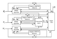
The attitude control block diagram of the eight-rotor system employing the robust BSMC with adaptive RBFNN method is depicted in Fig. 2. It is noted that the attitude control of the eight-rotor UAV is divided into three attitude channels,that is,pitch channel, roll channel and yaw channel. Each attitude channel is separately controlled by the proposed algorithm. For example with respect to the roll control channel,the design process of the proposed algorithm is described step-by-step as follows.
|
Download:
|
| Fig. 2. The attitude control block diagram with the proposed method. | |
The roll channel is represented as
| $ \begin{align} &\dot{x}_1=x_2, \nonumber\\ &\dot{x}_2=\frac{M_x}{I_x}+ D_x, \end{align} $ | (20) |
where $x_1$ denotes the state of roll angle,$x_2$ expresses the state of roll angle velocity. $D_x$ termed as the lumped uncertainties in the roll channel is given by
| $ \begin{equation} D_x = \tau_x + f_x, \end{equation} $ | (21) |
where $\tau_x=\Delta{M_x}/(I_x + \Delta{I_x})$ treated as the external disturbance in the roll channel is bounded, $f_x=-\Delta{I_x}M_x/[I_x(I_x + \Delta{I_x})]$ in the case when the inertia matrix uncertainty is considered as the model uncertainty.
Step 1.
For the sake of roll angle tracking objective,define the roll angle tracking error as
| $ \begin{equation} z_1 = x_{1d} - x_1, \end{equation} $ | (22) |
where $x_{1d}$ denotes the desired roll angle. And the derivative of $z_1$ is obtained by
| $ \begin{equation} \dot{z}_1 = \dot{x}_{1d} - x_2. \end{equation} $ | (23) |
Define the following stabilizing function
| $ \begin{equation} c_{1}=\alpha z_{1}, \end{equation} $ | (24) |
where $\alpha$ is a positive constant. The first Lyapunov function is chosen as
| $ \begin{equation} V_{1}=\frac{z_{1}^{2}}{2}. \end{equation} $ | (25) |
Define the roll angle velocity tracking error as $z_{2}=x_{2}-\dot{x}_{1d}-c_{1}$,then the derivative of $V_{1}$ is
| $ \begin{equation} \dot{V}_{1}=z_{1}(\dot{x}_{1d}-x_{2})=-z_{1}z_{2}-\alpha z_{1}^{2}. \end{equation} $ | (26) |
Step 2.
The derivative of $z_{2}$ is now expressed as
| $ \begin{align} &\dot{z}_{2}=\dot{x}_{2}-\ddot{x}_{1d}-\alpha\dot{z_{1}}= \nonumber\\ &\quad \frac{M_{x}}{I_{x}} + D_{x} -\ddot{x}_{1d} +\alpha(z_{2}+\alpha z_{2}). \end{align} $ | (27) |
Then,the following Lyapunov function is defined by
| $ \begin{equation} V_{2}=V_{1} + \frac{1}{2}s^{2}, \end{equation} $ | (28) |
with the sliding surface designed as
| $ \begin{equation} s=kz_{1}+z_{2}, \end{equation} $ | (29) |
where $k$ is a positive constant. Then by substituting (26),(27) and (29) into (28),it can be derived that
| $ \begin{align} &\dot{V}_{2}=\dot{V}_{1}+ s\dot{s}=-z_{1}z_{2}-\alpha z_{1}^{2} + s(kz_{1}+z_{2})= \nonumber\\ &\quad-z_{1}z_{2}-\alpha z_{1}^{2} +s[(k-\alpha)\dot{z_{1}}+ \frac{M_{x}}{I_{x}}+ D_{x}-\ddot{x}_{1d}]. \end{align} $ | (30) |
Step 3.
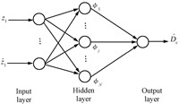
Since the lumped uncertainty $D_x$ in the roll channel is unknown in practical application,the bound is difficult to determine. Thereby,an adaptive RBFNN uncertainty observer is proposed to adapt the estimated value of the lumped uncertainty $\hat{D}_x$. The structure of RBFNN with receptive field units is shown in Fig. 3 and the receptive field function is usually a Gaussian function or a logarithmic function[16]. If the Gaussian function is selected as the receptive field function in the roll channel and the input vector of RBFNN is $\pmb{Z}=[z_{1},\dot{z}_{1}]^{\rm{T}}$,then the output is derived as follows using the weighted sum method
| $ \begin{equation} \hat{D}_{x}=\sum_{j=1}^{N}W_{j}\phi_{j}(\pmb{Z}),\quad j=1,2,\cdots,N, \end{equation} $ | (31) |
| $ \begin{equation} \phi_{j}(\pmb{Z})=\exp(-\frac{\|\pmb{Z}-M_{j}\|^2}{{\sigma_{j}}^{2}}), \end{equation} $ | (32) |
|
Download:
|
| Fig. 3. The structure of RBFNN in the roll channel. | |
where $W_j$ is the connective weight between the hidden layer and the output layer. $N$ denotes the number of hidden nodes. And each hidden node contains a centre vector expressed by $M_j$ and a positive scalar called the width expressed by $\sigma_j$.
To develop the adaptation laws of the RBFNN uncertainty observer, define minimum reconstructed error $\sigma_x$ in the roll channel as
| $ \begin{equation} \sigma_x=D_x - \hat{D}_x(\pmb{W^{*}}), \end{equation} $ | (33) |
where $\pmb{W^{*}}$ is an optimal weight vector that achieves the minimum reconstructed error. Then,a Lyapunov candidate is chosen as
| $ \begin{equation} V_{3}=V_{2}+\frac{1}{2\eta_1}(\pmb{W^{*}}-\pmb{W})^{\rm{T}}(\pmb{W^{*}}-\pmb{W})+ \frac{1}{2\eta_2}(\delta_x-\hat{\delta}_x)^{2}, \end{equation} $ | (34) |
where $\eta_1$ and $\eta_2$ are positive constants, $\hat{\delta}_x$ denotes the estimated value of the minimum reconstructed error. $\delta_x$ is provided to compensate the observed error induced by the RBFNN uncertainty observer and to further guarantee the stable characteristic of the attitude control system for the eight-rotor UAV.
Then,the derivative of the Lyapunov function $V_3$ is expressed by
| $ \begin{equation}\begin{split} &\dot{V}_{3}=\dot{V}_{2}-\frac{1}{\eta_{1}}(\pmb{W^{*}}-\pmb{W})^{\rm{T}}\dot{W}- \frac{1}{\eta_2}(\delta_x-{\hat{\delta}}_{x}){\dot{\hat{\delta}}}_{x} =\\ &\quad-z_{1}z_{2}-\alpha z_{1}^{2}+s[(k-\alpha)\dot{z_{1}}+ \frac{M_{x}}{I_{x}}+D_{x}-\ddot{x}_{1d}]- \\ &\quad\frac{1}{\eta_{1}}({\pmb{W}}^{*}-\pmb{W})^{\rm{T}}\dot{\pmb{W}}-\frac{1}{\eta_{2}} (\delta_{x}-{\hat{\delta}}_x){\dot{\hat{\delta}}}_x. \end{split} \end{equation} $ | (35) |
Consequently,the robust backstepping sliding-mode control law $U_{x}$ that is equal to $M_{x}$ of the eight-rotor system is designed as
| $ \begin{align} &U_{x}=M_x=\nonumber\\ &\quad I_{x}[-(k-\alpha)\dot{z}_1+\ddot{x}_{1d}-\gamma s -h{\rm{sgn}}(s)- U_H - U_R], \end{align} $ | (36) |
in which $\gamma,h$ are positive constants,the robust controller $U_{H}$ is redesigned as (37) and $U_R$ is a compensated controller designed as (38)
| $ \begin{align} &U_{H}=\hat{D}_{x}(W), \end{align} $ | (37) |
| $ \begin{align} &U_R=\hat{\delta}_{x}. \end{align} $ | (38) |
Accordingly,the derivative of the Lyapunov function is derived by
| $ \begin{equation}\begin{split} &\dot{V}_{3}=-z_{1}z_{2}-\alpha {z_{1}}^{2}-\gamma s^{2} -h|s|+s[D_{x}-\hat{D}_{x}(\pmb{W}^{*})-\hat{\delta}_{x}]- \\ &\frac{1}{\eta_{2}}(\delta_{x}-{\hat{\delta}}_{x}){\dot{\hat{\delta}}}_{x}+ s[\hat{D}_{x}({\pmb{W}}^{*})-\hat{D}_{x}(\pmb{W})]-\frac{1}{\eta_{1}}(\pmb{W}^{*}-\pmb{W})^{\rm{T}}\dot{\pmb{W}}. \end{split} \end{equation} $ | (39) |
If the adaptation laws for $\dot{\pmb{W}}$ and ${\dot{\hat{\delta}}}_{x}$ are designed as follows
| $ \begin{align} &\dot{\pmb{W}}=s\eta_{1}\phi(\pmb{Z}), \end{align} $ | (40) |
| $ \begin{align} &{\dot{\hat{\delta}}}_x=s\eta_{2}. \end{align} $ | (41) |
Then the derivative of the Lyapunov function $V_{3}$ can be rewritten as
| $ \begin{align} &\dot{V}_{3}=-z_{1}z_{2}-\alpha {z_{1}}^{2}-\gamma s^{2}-h|s|= \nonumber\\ &\quad -z^{\rm{T}}\Lambda z-h|s|, \end{align} $ | (42) |
where $\Lambda$ is a symmetric matrix with the following form
| $ \begin{equation} \Lambda=\left[ \begin{array}{cc} \alpha+\gamma k^{2}& \gamma k +\displaystyle\frac{1}{2} \\ \gamma k +\displaystyle\frac{1}{2} & \gamma \\ \end{array} \right]. \end{equation} $ | (43) |
According to Barbalat$'$s lemma[14, 17],it is noted that $\dot{V}_{3}\leq0$ when $\Lambda$ is guaranteed to be positive definite as expressed by
| $ \begin{equation} |\Lambda|=\gamma(\alpha-k)-\frac{1}{4}>0. \end{equation} $ | (44) |
Thereby,the eight-rotor control system in the roll channel is asymptotically stable in the case of the above condition despite the presence of model uncertainties and external disturbances without the knowledge of bounds. Furthermore,the attitude control in pitch channel and yaw channel with the proposed method have the same design procedure,which is not described for the sake of simplicity.
Ⅳ. NUMERICAL SIMULATIONS RESULTSIn this section,simulations for the attitude control of the coaxial eight-rotor UAV are performed to demonstrate the validity of the proposed BSMC with adaptive RBFNN method in the face of model uncertainties and external disturbances with unknown bounds. Furthermore,the performance of the proposed control algorithm and BSMC algorithm are compared to verify the improvement on robustness of the proposed control algorithm. The parameters of dynamic model in the simulations are taken from the eight-rotor prototype,as listed in Table Ⅰ.
|
|
Table Ⅰ THE PARAMETERS OF THE EIGHT-ROTOR PROTOTYPE |
An uncertainty of $-30\,\%$ in the inertia matrix is assumed as the model uncertainties,i.e.,$\Delta I=[-0.3I_{x},-0.3I_{y},-0.3I_{z}]^{\rm{T}}$. In addition,the constant external disturbance and the time-varying external disturbance given by $\tau_{d1}=0.4$ and $\tau_{d2}=0.2{\rm\sin}(0.5t)$ are considered to act on the pitch, roll as well as yaw control,respectively.
To investigate the effectiveness of the proposed algorithm,two simulated cases of different desired attitude angles are considered with the same initial attitude angles as ${{\pmb\eta}_{0}}$=[0,0,0]T degree in the following:
Case 1. ${{\pmb\eta}_{d}}$=[12,13,14]T degree
Case 2. ${{\pmb\eta}_{d}}=[12\cos(t),12\cos(t),30\cos(t)]^{\rm{T}}$ degree
The parameters of backstepping sliding-mode control are tuned as follows to achieve the favorable transient control performance,and at the same time to guarantee the great steady-state performance along with satisfying the stability condition described in (44).
Roll channel: $\alpha_{x}=10,k_{x}=0.5,\gamma_{x}=15,h_{x}=1$,
Pitch channel: $\alpha_{y}=15,k_{y}=0.5,\gamma_{y}=25,h_{y}=4$,
Yaw channel: $\alpha_{z}=12,k_{z}=0.5,\gamma_{z}=20,h_{z}=1$,
where $\alpha$ has an influence on the response speed of system,while excessive increase will degenerate the system stability. Additionally,the significant reduction of $k$ leads to the increasing steady-state error,and it will produce jerk in the system when it goes up too high. $\gamma$ decides the convergent speed to approach the sliding surface,but its dramatic increase can worsen the stability performance. $h$ can guarantee to reach the sliding surface in a limited time,in the meantime,a much larger value will cause greater chattering.
In addition,the number of the hidden nodes in the adaptive RBFNN observer is set to 6,the centre and the width in each hidden node is chosen as $m=3$ and $\sigma=7$,respectively. Moreover,the adaptive coefficients are taken as $\eta_{1}=10$ and $\eta_{2}=3$. All these parameters are given to achieve a better estimation performance by trial and error.
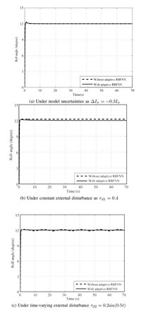
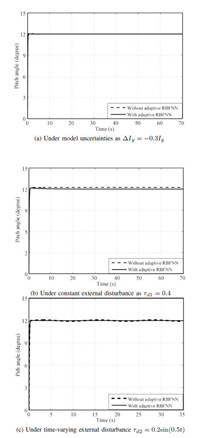
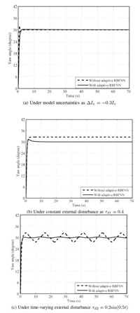
A. Numerical Simulations Result For Case 1Firstly,the simulation for comparing attitude control through the proposed method and BSMC method for Case 1 is operated with model uncertainties,along with constant external disturbance as well as time-varying external disturbance,as shown in Fig. 4,Fig. 5, Fig. 6,respectively. Additionally,to make a quantitative comparison of the results attained by the two control algorithms, some attitude control performance indices in Case 1 are elaborated in Table II,where $Roll_{ij},Pitch_{ij}$,and $Yaw_{ij}$,$i=1,2$, $j=1,2,3$,respectively denote three attitude controls. The control channel with the proposed method is represented by $i=1$ while with BSMC method by $i=2$. Besides,$j=1,2,3$ expresses the different uncertainties in turn,that is,model uncertainty,constant external disturbance and time-varying external disturbance.
|
|
Table Ⅱ ATTITUDE CONTROL PERFORMANCE INDICES IN THE CASE Ⅰ |
|
Download:
|
| Fig. 4. Roll angle comparison result between BSMC with adaptive RBFNN and BSMC in Case 1. | |
|
Download:
|
| Fig. 5. Pitch angle comparison result between BSMC with adaptive RBFNN and BSMC in Case 1. | |
|
Download:
|
| Fig. 6. Yaw angle comparison result between BSMC with adaptive RBFNN and BSMC in Case 2. | |
Therefore,it can be clearly obtained that all the attitude angles subjected to the constant disturbance have a remarkable steady-state error with BSMC algorithm,while the steady-state error is thoroughly eliminated using the proposed algorithm due to the fact that adaptive RBFNN successfully estimates and compensates the constant disturbance. As such,faced with the time-varying disturbance,three attitude control performances suffer from significantly less deterioration with the proposed method than that with BSMC method. While there is relatively little difference between the two methods under inertia matrix uncertainty. Moreover,it is worth noting that the yaw angle control performance deteriorates more seriously than the other attitude control performances using the BSMC method in the case of disturbances. The phenomenon probably results from the weaker drive ability on the yaw movement as compared to the other attitude movements.
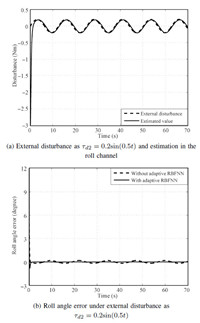
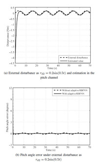
B. Numerical Simulations Result For Case 2Next,to test the robustness of the proposed method,the disturbance estimation and attitude angles error comparison simulations in Case 2 with $\tau_{d2}$ are presented in Fig. 7, Fig. 8 and Fig. 9,from which it can be seen that the proposed method provides better control performance against external disturbance over BMSC method.
|
Download:
|
| Fig. 7. Disturbance estimation and roll angle error comparison between the proposed method and BSMC method in Case 2. | |
|
Download:
|
| Fig. 8. Disturbance estimation and pitch angle error comparison between the proposed method and BSMC method in Case 2. | |
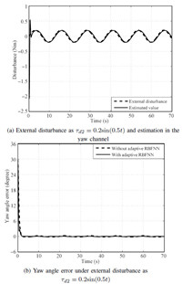
|
Download:
|
| Fig. 9. Disturbance estimation and yaw angle error comparison between the proposed method and BSMC method in Case 2. | |
Fig. 7 (b) shows that the roll angle error based on the proposed method is dramatically limited of the order of about $\pm0.005$ degree than that of BSMC method which has an error of about $\pm0.6$ degree. Similarly,Fig. 8 (b) illustrates pitch angle error utilizing the proposed method is controlled in the interval as $\pm0.006$ degree,while it ranges at $\pm0.011$ degree using the BSMC algorithm. Besides,the proposed method in the yaw control channel also has smaller yaw error of about $\pm0.017$ degree than BSMC method with yaw error of approximately $\pm0.0126$ degree,as shown in Fig. 9 (b). Furthermore,the satisfactory estimation performance against the external disturbance with the adaptive RBFNN observer is definitely corroborated in attitude control,as described in Fig. 7 (a), Fig. 8 (a) and Fig. 9 (a).
Hence simulation results highlight the claim that BSMC with adaptive RBFNN algorithm can offer the greater attitude control performance and the stronger robustness as compared to BSMC algorithm in the presence of model uncertainties and external disturbances. It is evident that the proposed method is better suited in dealing with the robust control problem of the uncertain eight-rotor UAV.
Ⅴ. CONCLUSIONIn this paper,the robust attitude control strategy is presented for a novel coaxial eight-rotor UAV. The novel eight-rotor UAV is modeled for the very first time to the best of our knowledge which offers remarkable advantages with respect to increased ability of disturbance rejection,greater payload capacity and damage tolerance over quad-rotor in condition of using the same type of motors and rotors.
On this basis,a robust backstepping sliding-mode controller with adaptive radial basis function neural network method is proposed to control the attitude of the eight-rotor UAV involving the model uncertainties and external disturbances. The proposed strategy with the simplified design has excellently greater robustness against disturbances than BSMC method. And the adaptive RBFNN observer can effectively estimate the lumped uncertainties with the compensation of the approximation error for the eight-rotor UAV,where the bounds of uncertainties are not required for the controller design. Besides,the uniformly ultimate stability of the eight-rotor system is proved using Lyapunov stability theorem.
Finally,simulation results demonstrate that the proposed method adopted in the novel coaxial eight-rotor UAV has better control performance and significantly greater robustness than backstepping sliding mode control method,where the inertia matrix uncertainty as model uncertainty,constant external disturbance and time-varying external disturbance are taken into account.
| [1] | Zuo Z. Trajectory tracking control design with command-filtered compensation for a quadrotor. IET Control Theory Applications, 2009, 4(11):2343-2355 |
| [2] | Dierks T, Jagannathan S. Output feedback control of a quadrotor UAV using neural networks. IEEE Transactions on Neural Networks, 2010, 21(1):50-66 |
| [3] | Chen Zong-Ji, Zhang Ru-Lin, Zhang Ping, Zhou Rui. Flight control:chanllenges and opportunities. Acta Automatica Sinica, 2013, 39(6):703-710(in Chinese) |
| [4] | Besnard L, Shtessel Y B, Landrum B. Quadrotor vehicle control via sliding mode controller driven by sliding mode disturbance observer. Journal of the Franklin Institute, 2012, 349(2):658-684 |
| [5] | Raffo G V, Ortega M G, Rubio F R. An integral predictive/nonlinear H∞ control structure for a quadrotor helicopter. Automatica, 2010, 46(1):29-39 |
| [6] | Mohammadi M, Shahri A M. Adaptive nonlinear stabilization control for a quadrotor UAV:theory, simulation and experimentation. Journal of Intelligent & Robotic Systems, 2013, 72(1):105-122 |
| [7] | Vega L L, Toledo B C, Loukianov A G. Robust block second order sliding mode control for a quadrotor. Journal of the Franklin Institute, 2012, 349(2):719-739 |
| [8] | Satici A C, Poonawala H, Spong M W. Robust optimal control of quadrotor UAVs. IEEE Access, 2013, 1:79-93 |
| [9] | Liu H, Bai Y Q, Lu G, Zhong Y S. Robust attitude control of uncertain quadrotors. IET Control Theory and Applications, 2013, 7(11):1583-1589 |
| [10] | Ryan T, Kim H J. LMI-based gain synthesis for simple robust quadrotor control. IEEE Transactions on Automation Science and Engineering, 2013, 10(4):1173-1178 |
| [11] | Li Shi-Hua, Ding Shi-Hong, Tian Yu-Ping. A finite-time state feedback stabilization method for a class of second order nonlinear systems. Acta Automatica Sinica, 2007, 33(1):101-104(in Chinese) |
| [12] | Das A, Lewis F, Subbarao K. Backstepping approach for controlling a quadrotor using Lagrange form dynamics. Journal of Intelligent & Robotic Systems, 2009, 56(1-2):127-151 |
| [13] | Cong B L, Liu X D, Chen Z. Backstepping based adaptive sliding mode control for spacecraft attitude maneuvers. Aerospace Science and Technology, 2013, 30(1):1-7 |
| [14] | Lin F J, Shen P H, Hsu S P. Adaptive backstepping sliding mode control for linear induction motor drive. Electric Power Applications, 2002, 149(3):184-194 |
| [15] | Wang Jia-Jun. Sliding mode backstepping control of induction motor based on self-recurrent wavelet neural networks. Acta Automatica Sinica, 2013, 35(1):1-8(in Chinese) |
| [16] | Roger Jang J S, Sun C T. Functional equivalence between radial basis function networks and fuzzy inference systems. IEEE Transactions on Neural Network, 1933, 4(1):156-159 |
| [17] | Slotine J J E, Li W P. Applied Nonlinear Control. New Jersey:Prentice-Hall, 1991. 122-126 |
 2015, Vol.2


